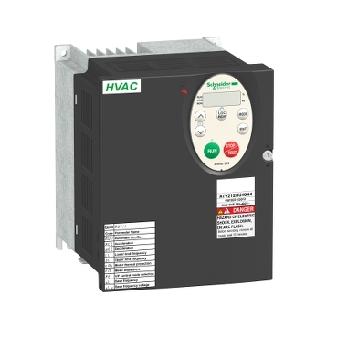

variable speed drive ATV212 - 5.5kW - 7.5hp - 480V - 3ph - EMC - IP21
Mfr. Part No.:
ATV212HU55N4
APT Stock No.:
SE-ATV212HU55N4
Brand:
SCHNEIDER ELECTRIC
In Stock: available
Need additional quantities?
Contact us for estimated lead timeSubtotal (1 unit)**
GHS 12,487.05
(Exc. VAT)
GHS 15,221.71
(Inc. VAT)
Available For Order
* Delivery dates may change based on your quantity and address.
Shipping & Policy
Payment Methods:


Shipping Cost:
Contact the supplier about freight and estimated delivery time.
Secure payments:
Every payment you make on aptghana.com is protected by the platform.
Return policy
Enjoy peace of mind with our 7-day return policy for used items, provided they are returned in their original packaging.
Centralized technical management
Instant viewing of the energy consumption
User-friendly
Compact size
Simple maintenance
Description
This Altivar 212 variable speed drive can feed 3-phase asynchronous motors. Its protection index is IP21 and it has a built-in EMC filter. It works at a rated power up to 5.5kW / 7.5hp and a rated voltage from 380V to 480V AC. Its design is based on eco-energy with a reduction in energy consumption of up to 70% compared to a conventional control system. Thanks to its cable temperature rise reduction technology, the Altivar 212 drive offers immediate, disturbance-free operation avoiding additional options such as a line choke or DC choke to deal with current harmonics. It weighs 3.35kg and its dimensions are, 142mm wide, 184mm high, 150mm deep. It is specifically designed for the most common fluid management applications in tertiary sector buildings (HVAC) like heating, ventilation, air conditioning and pumping. It conforms to international standards IEC/EN 61800-5-1 and IEC/EN 61800-3 (immunity and conducted and radiated EMC emissions). It is also CE, UL, CSA, C-Tick and NOM certified. The Altivar 212 offers optional motor chokes which can increase the maximum cable lengths between the drive and the motor and limit disturbance at the motor terminals. It is designed to be mounted in vertical position (+/- 10 °) on a panel, thanks to 4 fixing holes. The Altivar 212 drive can easily be adapted to all building management systems thanks to its numerous functions and communication protocols integrated as standard, Modbus, METASYS N2, APOGEE FLN P1 and BACnet. complies with directives such as RoHS, WEEE

Shipping & Policy
Payment Methods:
Shipping Cost:
Contact the supplier about freight and estimated delivery time.
Secure payments:
Every payment you make on aptghana.com is protected by the platform.
Return policy
Enjoy peace of mind with our 7-day return policy for used items, provided they are returned in their original packaging.
Compatible products
Accessories (1)
Specifications
| Main | |
|---|---|
| Device short name | ATV212 |
| Product destination | Asynchronous motors |
| Network number of phases | 3 phases |
| Motor power kW | 5.5 kW |
| Motor power hp | 7.5 hp |
| Supply voltage limits | 323…528 V |
| Supply frequency | 50...60 Hz - 5...5 % |
| Line current | 10.9 A at 380 V 8.6 A at 480 V |
| Range of product | Altivar 212 |
| Product or component type | Variable speed drive |
| Product specific application | Pumps and fans in HVAC |
| Communication port protocol | METASYS N2 LonWorks BACnet Modbus APOGEE FLN |
| [Us] rated supply voltage | 380...480 V - 15...10 % |
| EMC filter | Class C2 EMC filter integrated |
| IP degree of protection | IP21 |
| Complementary | |
|---|---|
| Apparent power | 9.1 kVA at 380 V |
| Continuous output current | 12 A at 380 V 12 A at 460 V |
| Maximum transient current | 13.2 A for 60 s |
| Speed drive output frequency | 0.5…200 Hz |
| Speed range | 1…10 |
| Speed accuracy | +/- 10 % of nominal slip 0.2 Tn to Tn |
Dimensions Drawings

Dimensions in mm
ATV212H | a | b | G | H | J | K | Ø |
|---|---|---|---|---|---|---|---|
075M3X...U22M3X 075N4...U22N4 | 107 | 143 | 93 | 121.5 | 5 | 16.5 | 2 x Ø5 |
U30M3X, U40M3X U30N4...U55N4 | 142 | 184 | 126 | 157 | 6.5 | 20.5 | 4 x Ø5 |
Dimensions in in.
ATV212H | a | b | G | H | J | K | Ø |
|---|---|---|---|---|---|---|---|
075M3X...U22M3X 075N4...U22N4 | 4.21 | 5.63 | 3.66 | 4.78 | 0.20 | 0.65 | 2 x Ø0.20 |
U30M3X, U40M3X U30N4...U55N4 | 5.59 | 7.24 | 4.96 | 6.18 | 0.26 | 0.81 | 4 x Ø0.20 |
Plate for EMC mounting (supplied with the drive)

Dimensions in mm
ATV212H | b1 | c |
|---|---|---|
075M3X...U22M3X 075N4...U22N4 | 49 | 67.3 |
U30M3X, U40M3X U30N4...U55N4 | 48 | 88.8 |
Dimensions in in.
ATV212H | b1 | c |
|---|---|---|
075M3X...U22M3X 075N4...U22N4 | 1.93 | 2.65 |
U30M3X, U40M3X U30N4...U55N4 | 1.89 | 3.50 |
Mounting and Clearance
Depending on the conditions in which the drive is to be used, its installation will require certain precautions and the use of appropriate accessories.
Install the unit vertically:
Do not place it close to heating elements.
Leave sufficient free space to ensure that the air required for cooling purposes can circulate from bottom to the top of the unit.

Type A mounting

Type B mounting

Type C mounting

By removing the protective blanking cover from the top of the drive, the degree of protection for the drive becomes IP21. The protective blanking cover may vary according to the drive model, see opposite.
,
To help ensure proper air circulation in the drive:
Fit ventilation grilles.
Check that there is sufficient ventilation. If there is not, install a forced ventilation unit with a filter. The openings and/or fans must provide a flow rate at least equal to that of the drive fans (refer to the product characteristics).

Use special filters with UL Type 12/IP54 protection.
Remove the blanking cover from the top of the drive.
The drive must be mounted in a dust and damp proof enclosure in certain environmental conditions, such as dust, corrosive gases, high humidity with risk of condensation and dripping water, splashing liquid, etc.This enables the drive to be used in an enclosure where the maximum internal temperature reaches 50°C.
Connections and Schema

NOTE: All terminals are located at the bottom of the drive. Install interference suppressors on all inductive circuits near the drive or connected on the same circuit, such as relays, contactors, solenoid valves, fluorescent lighting, etc.
Voltage/current selection for analog I/O (VIA and VIB)

Voltage/current selection for analog I/O (FM)

Selection of logic type

,
"Source" position

"Sink" position

"PLC" position with PLC transistor outputs | |
(1) PLC |
(1) PLC |


2-wire control

3-wire control

PTC probe

Voltage analog inputs
External +10 V | |
(2) ATV 212 control terminals (4) Speed reference potentiometer 2.2 to 10 kΩ |
(2) ATV 212 control terminals |


Analog input configured for current: 0-20 mA, 4-20 mA, X-Y mA

Analog input VIA configured as positive logic input ("Source" position)

Analog input VIA configured as negative logic input ("Sink" position)

Performance Curves
The derating curves for the drive nominal current (In) depend on the temperature, the switching frequency and the mounting type (A, B or C).
For intermediate temperatures (45°C for example), interpolate between 2 curves.