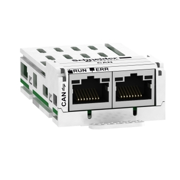
ATV320 4KW 380..500V 3PH COMPACT
Mfr. Part No.:
ATV320U40N4C
APT Stock No.:
SE-ATV320U40N4C
Brand:
SCHNEIDER ELECTRIC
In Stock: available
Need additional quantities?
Contact us for estimated lead timeSubtotal (1 unit)**
(Exc. VAT)
(Inc. VAT)
Available For Order
* Delivery dates may change based on your quantity and address.
Shipping & Policy
Payment Methods:



Shipping Cost:
Contact the supplier about freight and estimated delivery time.
Secure payments:
Every payment you make on aptghana.com is protected by the platform.
Return policy
Enjoy peace of mind with our 7-day return policy for used items, provided they are returned in their original packaging.
Save time and space
Less downtime and maintenance costs
Optimized for ventilation and pumping applications: up to 30% energy savings
Advanced connectivity reduce your initial investment while keeping flexibility in design
Control of asynchronous and synchronous motors, including IE2, IE3 and PM motors
Description

Shipping & Policy
Payment Methods:
Shipping Cost:
Contact the supplier about freight and estimated delivery time.
Secure payments:
Every payment you make on aptghana.com is protected by the platform.
Return policy
Enjoy peace of mind with our 7-day return policy for used items, provided they are returned in their original packaging.
Compatible products
Specifications
Dimensions Drawings


Mounting and Clearance

Only Possible at Ambient Temperature Less or Equal to 50 °C (122 °F)


For Operation at Ambient Temperature Above 50 °C (122 °F)
Connections and Schema

(1) Line choke (if used)
(2) Use relay output R1 set to operating state Fault to switch Off the product once an error is detected.

(1) Line choke (if used)
(2) Use relay output R1 set to operating state Fault to switch Off the product once an error is detected.
,

(1) Analog output
(2) Analog inputs
(3) Potentiometer SZ1RV1202 (2.2 kΩ) or similar (10 kΩ maximum)
(4) Digital Inputs - Shielding instructions are given in the Electromagnetic Compatibility section
,
Switch Set to SRC (Source) Position Using the Output Power Supply for the Digital Inputs

Switch Set to SRC (Source) Position and Use of an External Power Supply for the Digital Inputs

Switch Set to SK (Sink) Position Using the Output Power Supply for the Digital Inputs

Switch Set to EXT Position Using an External Power Supply for the Digital Inputs

NOTE :
• STO input is also connected by default on a 24 Vdc terminal. If the external power supply is switched off, the function STO will be triggered.
• To avoid triggering the STO function when switching-on the product, the external power supply must be previously switched on.
Performance Curves

 40 °C (104 °F) - Mounting type A, B and C
 50 °C (122 °F) - Mounting type C
 60 °C (140 °F) - Mounting type C
In : Nominal Drive Current
SF : Switching Frequency