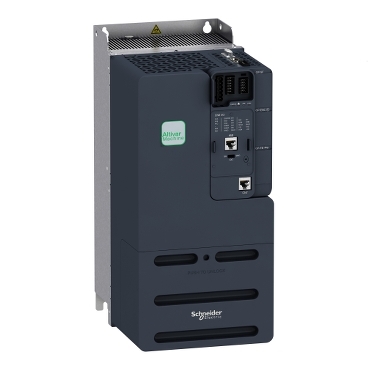
variable speed drive - 11kW- 400V - 3 phases - ATV340
Mfr. Part No.:
ATV340D11N4
APT Stock No.:
SE-ATV340D11N4
Brand:
SCHNEIDER ELECTRIC
In Stock: available
Need additional quantities?
Contact us for estimated lead timeSubtotal (1 unit)**
GHS 17,703.90
(Exc. VAT)
GHS 21,581.05
(Inc. VAT)
Available For Order
* Delivery dates may change based on your quantity and address.
Shipping & Policy
Payment Methods:


Shipping Cost:
Contact the supplier about freight and estimated delivery time.
Secure payments:
Every payment you make on aptghana.com is protected by the platform.
Return policy
Enjoy peace of mind with our 7-day return policy for used items, provided they are returned in their original packaging.
Powerful dynamism for superior machine performance
Unprecedented automation performance
Reduced machine design time
Simplified machine engineering
Seamless automation integration
Description

Shipping & Policy
Payment Methods:
Shipping Cost:
Contact the supplier about freight and estimated delivery time.
Secure payments:
Every payment you make on aptghana.com is protected by the platform.
Return policy
Enjoy peace of mind with our 7-day return policy for used items, provided they are returned in their original packaging.
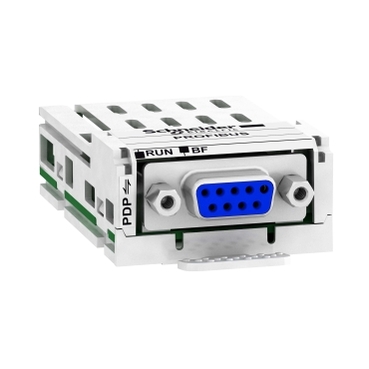
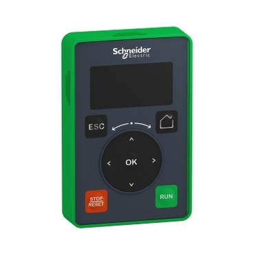
Compatible products
Specifications
Dimensions Drawings

Mounting and Clearance

Dimensions in mm
X1 | X2 | X3 |
|---|---|---|
|
|
|
Dimensions in in.
X1 | X2 | X3 |
|---|---|---|
|
|
|
,

Possible, at ambient temperature ≤ 50 °C (122 °F)


Connections and Schema
Connection diagrams conforming to standards ISO13849 category 1 and IEC/EN 61508 capacity SIL1, stopping category 0 in accordance with standard IEC/EN 60204-1.


It is possible to connect either 1 or 3 sensors on terminals AI1.
,

,
Using DISUP Signal

In SRC position DISUP outputs 24 V. In SK position DISUP is connected to 0 V.
Positive Logic, Source, European Style

Negative Logic, Sink, Asian Style

Negative Logic, Sink, Asian Style

,
Positive Logic, Source, European Style, DQCOM to +24V

Negative Logic, Sink, Asian Style, DQCOM to 0V

Positive Logic, Source, European Style, DQCOM to +24V

Negative Logic, Sink, Asian Style, DQCOM to 0V

Performance Curves

,