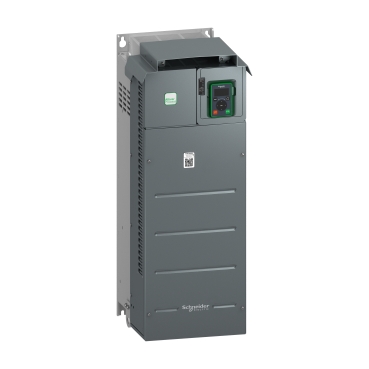
ATV610-ND 90kW/125HP- HD 75KW/100HP- 380...415V
Mfr. Part No.:
ATV610D90N4
APT Stock No.:
SE-ATV610D90N4
Brand:
SCHNEIDER ELECTRIC
In Stock: available
Need additional quantities?
Contact us for estimated lead timeSubtotal (1 unit)**
GHS 61,186.44
(Exc. VAT)
GHS 73,423.73
(Inc. VAT)
Available For Order
* Delivery dates may change based on your quantity and address.
Shipping & Policy
Payment Methods:


Shipping Cost:
Contact the supplier about freight and estimated delivery time.
Secure payments:
Every payment you make on aptghana.com is protected by the platform.
Return policy
Enjoy peace of mind with our 7-day return policy for used items, provided they are returned in their original packaging.
Description

Shipping & Policy
Payment Methods:
Shipping Cost:
Contact the supplier about freight and estimated delivery time.
Secure payments:
Every payment you make on aptghana.com is protected by the platform.
Return policy
Enjoy peace of mind with our 7-day return policy for used items, provided they are returned in their original packaging.
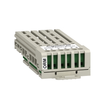
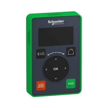
Compatible products
Specifications
Dimensions Drawings

Drawings from left to right: rear view, right side view with top cover, right side view without top cover.

Drawings from left to right: rear view, right side view with top cover.
Mounting and Clearance

• Mount the device in a vertical position. This is required for cooling the device.
• Attach it on the mounting surface in compliance with standards, using 4 screws with captive washer.
• The use of washers is required with all mounting screws.
• Tighten the fixation screws.
• Do not mount the device close to heat sources.
• Avoid environmental effects like high temperatures and high humidity as well as dust, dirt and conductive gases.
• Adhere to the minimum installation distances for required cooling.
• Do not mount the device on flammable materials.
,

a ≥ = 110 mm (4.33 in.)


a ≥ = 110 mm (4.33 in.)
Connections and Schema

(1) Line choke (if used).
(2) Use relay output R1 set to operating state Fault to switch Off the product once an error is detected.

(1) : Digital Inputs
(2) : Reference potentiometer
(3) : Analog inputs
(4) : -10...+10 Vdc
(5) : Analog outputs

It is possible to connect either 1 sensors on terminals AI2 or AI3.
Performance Curves

In : Nominal Drive Current
SF : Switching Frequency