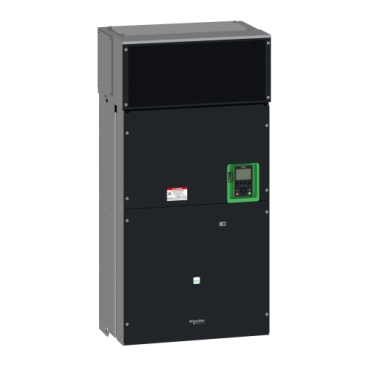

Variable speed drive, Altivar Process ATV600, ATV630, 315kW/500 hp, 380...480 V, IP00
Mfr. Part No.:
ATV630C31N4
APT Stock No.:
SE-ATV630C31N4
Brand:
SCHNEIDER ELECTRIC
In Stock: available
Need additional quantities?
Contact us for estimated lead timeSubtotal (1 unit)**
GHS 260,501.40
(Exc. VAT)
GHS 317,551.21
(Inc. VAT)
Available For Order
* Delivery dates may change based on your quantity and address.
Shipping & Policy
Payment Methods:


Shipping Cost:
Contact the supplier about freight and estimated delivery time.
Secure payments:
Every payment you make on aptghana.com is protected by the platform.
Return policy
Enjoy peace of mind with our 7-day return policy for used items, provided they are returned in their original packaging.
Embedded power measurement and energy dashboard
Embedded process monitoring and control
Stop and Go function to reduce energy consumption
Asset monitoring and protection
Drift monitoring
Description
This Altivar Process ATV600 variable speed drive can feed 3-phase synchronous and asynchronous power motors. It features 3 built-in RJ45 communication ports as standard, 1 Ethernet port, 2 serial ports. It works at a rated supply voltage from 380V to 480V AC. This drive provides up to 30% energy saving when on standby due to the innovative ''Stop and Go''operation without additional costs. It is suitable for motors with power rating up to 315kW / 500hp for applications requiring slight overload (up to 120%). It is suitable for motors with power rating up to 250kW / 400hp for applications requiring significant overload (up to 150%). It weighs 203kg and its dimensions are, 598mm wide, 1195mm high, 380mm deep. This drive is focused on fluids management processing and energy saving, it offers extensive flexibility in water and wastewater, mining, minerals and metals, oil and gas and food and beverage applications. Accessories (fan kit, graphic display terminal) and options (I/O expansion modules, communication modules, EMC input filters) are available with Altivar Process ATV600 drives, depending on the drive rating. It is designed to be mounted in vertical position (+/- 10 °) on a wall. This new concept of drives meets the major needs of process and utilities in terms of equipment efficiency and total cost of ownership by supporting the energy management, asset management and also the overall performance of the process.

Shipping & Policy
Payment Methods:
Shipping Cost:
Contact the supplier about freight and estimated delivery time.
Secure payments:
Every payment you make on aptghana.com is protected by the platform.
Return policy
Enjoy peace of mind with our 7-day return policy for used items, provided they are returned in their original packaging.
Compatible products
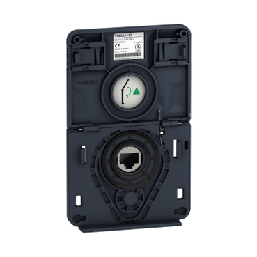
Accessories (1)
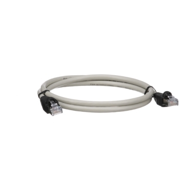
Cables (3)
Specifications
| Main | |
|---|---|
| Range of product | Altivar Process ATV600 |
| Product specific application | Process and utilities |
| Product or component type | Variable speed drive |
| Variant | Standard version |
| Device short name | ATV630 |
| Mounting mode | Wall mount |
| Communication port protocol | Modbus serial Ethernet Modbus TCP |
| [Us] rated supply voltage | 380...480 V - 15...10 % |
| [Us] rated supply voltage | 380...480 V |
| Relative symmetric mains voltage tolerance | 10 % |
| Relative symmetric network frequency tolerance | 5 % |
| Nominal output current | 616.0 A |
| IP degree of protection | IP21 |
| Product destination | Asynchronous motors Synchronous motors |
| EMC filter | Integrated with 50 m conforming to IEC 61800-3 category C3 |
| IP degree of protection | IP00 conforming to IEC 61800-5-1 IP00 conforming to IEC 60529 IP21 (with kit VW3A9113) conforming to IEC 61800-5-1 IP21 (with kit VW3A9113) conforming to IEC 60529 |
| type of cooling | Forced convection |
| Supply frequency | 50...60 Hz - 5...5 % |
| Motor power kW | 315 kW (normal duty) 250 kW (heavy duty) |
| Motor power hp | 500 hp normal duty 400 hp heavy duty |
| Line current | 569 A at 380 V (normal duty) 461 A at 480 V (normal duty) 457 A at 380 V (heavy duty) 375 A at 480 V (heavy duty) |
| Continuous output current | 616 A at 2.5 kHz for normal duty 481 A at 2.5 kHz for heavy duty |
| Speed drive output frequency | 0.1…500 Hz |
| Safety function | STO (safe torque off) SIL 3 |
| Option card | Slot A: communication module, Profibus DP V1 Slot A: communication module, PROFINET Slot A: communication module, DeviceNet Slot A: communication module, Modbus TCP/EtherNet/IP Slot A: communication module, CANopen daisy chain RJ45 Slot A: communication module, CANopen SUB-D 9 Slot A: communication module, CANopen screw terminals Slot A/slot B: digital and analog I/O extension module Slot A/slot B: output relay extension module Slot A: communication module, Ethernet IP/Modbus TCP/MD-Link Communication module, BACnet MS/TP Communication module, Ethernet Powerlink |
| Complementary | |
|---|---|
| Discrete input number | 8 |
| Discrete input type | DI7, DI8 programmable as pulse input: 0…30 kHz, 24 V DC (<= 30 V) |
| Discrete input logic | 16 preset speeds |
| Discrete output number | 0 |
| Discrete output type | Relay outputs R1A, R1B, R1C 250 V AC 3000 mA Relay outputs R1A, R1B, R1C 30 V DC 3000 mA Relay outputs R2A, R2C 250 V AC 5000 mA Relay outputs R2A, R2C 30 V DC 5000 mA Relay outputs R3A, R3C 250 V AC 5000 mA Relay outputs R3A, R3C 30 V DC 5000 mA |
| Analogue input number | 3 |
Dimensions Drawings
Rear, Right and Front Views


Mounting and Clearance

X1 | X2 | X3 |
|---|---|---|
≥ 200 mm (7.87 in.) | ≥ 150 mm (5.91 in.) | ≥ 10 mm (0.39 in.) |
,

a ≥ 0


a ≥ 0
Connections and Schema
Connection diagrams conforming to standards EN 954-1 category 1 and IEC/EN 61508 capacity SIL1, stopping category 0 in accordance with standard IEC/EN 60204-1

(1) Line choke if used
(2) Use relay R1 set to operating state Fault to switch Off the product once an error is detected.
A1 : Drive
KM1 : Line Contactor
Q2, Q3 : Circuit breakers
S1, S2 : Pushbuttons
T1 : Transformer for control part
,
Connection diagrams conforming to standards EN 954-1 category 1 and IEC/EN 61508 capacity SIL1, stopping category 0 in accordance with standard IEC/EN 60204-1

(1) Line choke if used
(2) Use relay R1 set to operating state Fault to switch Off the product once an error is detected.
A1 : Drive
KM1 : Contactor
,

(1) Safe Torque Off
(2) Analog Output
(3) Digital Input
(4) Reference potentiometer
(5) Analog Input
R1A, R1B, R1C : Fault relay
R2A, R2C : Sequence relay
R3A, R3C : Sequence relay
It is possible to connect either 1 or 3 sensors on terminals AI2 or AI3.

,
The switch is used to adapt the operation of the logic inputs to the technology of the programmable controller outputs.
Set the switch to Source (factory setting) if using PLC outputs with PNP transistors.
Set the switch to Ext if using PLC outputs with NPN transistors.


Performance Curves

 40 °C (104 °F)
 50 °C (113 °F)
 60 °C (140 °F)
In : Nominal Drive Current
SF : Switching Frequency