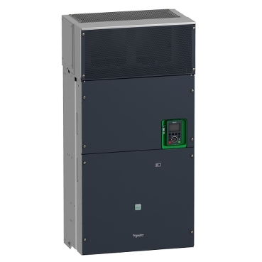

variable speed drive, ATV930, 315kW, 400/480V, w/o braking unit, IP00
Mfr. Part No.:
ATV930C31N4C
APT Stock No.:
SE-ATV930C31N4C
Brand:
Schneider Electric
Back Order
Need more stock?
Contact us for Est. Lead TimeSubtotal (1 unit)**
GHS 270,568.26
(Exc. VAT)
GHS 329,822.71
(Inc. VAT)
Available For Order
* Delivery dates may change based on your quantity and address.
Shipping & Policy
Payment Methods:


Shipping Cost:
Contact the supplier about freight and estimated delivery time.
Secure payments:
Every payment you make on aptghana.com is protected by the platform.
Return policy
Enjoy peace of mind with our 7-day return policy for used items, provided they are returned in their original packaging.
Embedded power measurement and energy dashboard
Embedded process monitoring and control
Stop and Go function to reduce energy consumption
Asset monitoring and protection
Drift monitoring
Description
This Altivar Process ATV900 variable speed drive can feed 3-phase synchronous and asynchronous power motors. It is suitable for motors with power rating up to 315kW/500hp for applications requiring slight overload (up to 120%). It is suitable for motors with power rating up to 250kW/400hp for applications requiring significant overload (up to 150%). It works at a rated supply voltage from 380V to 480V AC. This variable speed / frequency drive (VSD / VFD) is specifically designed for industrial processes. In the following market segments, oil and gas, mining, minerals and metals, food and beverage water and wastewater. It offers high motor performance on any motor and total control of any kind of coupling in master/slave applications. Network services help ensure operation continuity even in case of connection breakdown. Web server and data logging help reduce downtime through fast troubleshooting and preventive maintenance. Its advanced connectivity, including EtherNet/IP and Modbus TCP, allows deep integration into automation architectures. It is designed to be mounted in vertical position (+/- 10 °) on a wall.

Shipping & Policy
Payment Methods:
Shipping Cost:
Contact the supplier about freight and estimated delivery time.
Secure payments:
Every payment you make on aptghana.com is protected by the platform.
Return policy
Enjoy peace of mind with our 7-day return policy for used items, provided they are returned in their original packaging.
Compatible products
Options (4)
Specifications
| Main | |
|---|---|
| Range of product | Altivar Process ATV900 |
| Device application | Industrial application |
| Product or component type | Variable speed drive |
| Product destination | Asynchronous motors Synchronous motors |
| Product specific application | Process for industrial |
| Variant | Without braking chopper Standard version |
| Network number of phases | 3 phases |
| Mounting mode | Wall mount |
| Communication port protocol | EtherNet/IP Modbus serial Modbus TCP |
| [Us] rated supply voltage | 380...480 V - 15...10 % |
| Continuous output current | 616 A at 2.5 kHz for normal duty 481 A at 2.5 kHz for heavy duty |
| EMC filter | Integrated With EMC plate option |
| IP degree of protection | IP21 |
| Degree of protection | UL type 1 |
| option module | Slot A: communication module for Profibus DP V1 Slot A: communication module for PROFINET Slot A: communication module for DeviceNet Slot A: communication module for EtherCAT Slot A: communication module for CANopen daisy chain RJ45 Slot A: communication module for CANopen SUB-D 9 Slot A: communication module for CANopen screw terminals Slot A/slot B/slot C: digital and analog I/O extension module Slot A/slot B/slot C: output relay extension module Slot B: 5/12 V digital encoder interface module Slot B: analog encoder interface module Slot B: resolver encoder interface module communication module for Ethernet Powerlink |
| Discrete input logic | 16 preset speeds |
| Motor power kW | 315.0 kW for normal duty 250.0 kW for heavy duty |
| Asynchronous motor control profile | Variable torque standard Constant torque standard Optimized torque mode |
| Synchronous motor control profile | Permanent magnet motor Synchronous reluctance motor |
| Maximum output frequency | 599 Hz |
| Switching frequency | 1...8 kHz adjustable 2.5...8 kHz with derating factor |
| Nominal switching frequency | 2.5 kHz |
| Line current | 569.0 A at 380 V (normal duty) 457.0 A at 380 V (heavy duty) 461.0 A at 480 V (normal duty) 375.0 A at 480 V (heavy duty) |
| Apparent power | 351 kVA at 480 V (normal duty) 286 kVA at 480 V (heavy duty) |
| Maximum transient current | 739 A during 60 s (normal duty) 722 A during 60 s (heavy duty) |
| Network frequency | 50...60 Hz |
| Prospective line Isc | 50 kA |
| Complementary | |
|---|---|
| Discrete input number | 10 |
| Discrete input type | DI1...DI8 programmable, 24 V DC (<= 30 V), impedance: 3.5 kOhm DI7, DI8 programmable as pulse input: 0…30 kHz, 24 V DC (<= 30 V) STOA, STOB safe torque off, 24 V DC (<= 30 V), impedance: > 2.2 kOhm |
| Discrete output number | 2 |
| Discrete output type | Logic output DQ+ 0…1 kHz <= 30 V DC 100 mA Programmable as pulse output DQ+ 0…30 kHz <= 30 V DC 20 mA Logic output DQ- 0…1 kHz <= 30 V DC 100 mA |
| Analogue input number | 3 |
| Analogue input type | AI1, AI2, AI3 software-configurable voltage: 0...10 V DC, impedance: 30 kOhm, resolution 12 bits AI1, AI2, AI3 software-configurable current: 0...20 mA/4...20 mA, impedance: 250 Ohm, resolution 12 bits |
Dimensions Drawings
Rear, Right and Front View


Mounting and Clearance

X1 | X2 | X3 |
|---|---|---|
≥ 200 mm (7.87 in.) | ≥ 150 mm (5.91 in.) | ≥ 10 mm (0.39 in.) |
,

a ≥ 0


a ≥ 0
Connections and Schema
Connection diagrams conforming to standards EN 954-1 category 1 and IEC/EN 61508 capacity SIL1, stopping category 0 in accordance with standard IEC/EN 60204-1

(1) Line choke if used
(2) Use relay R1 set to operating state Fault to switch Off the product once an error is detected.
A1 : Drive
KM1 : Line Contactor
Q2, Q3 : Circuit breakers
S1, S2 : Pushbuttons
T1 : Transformer for control part
,
Connection diagrams conforming to standards EN 954-1 category 1 and IEC/EN 61508 capacity SIL1, stopping category 0 in accordance with standard IEC/EN 60204-1

(1) Line choke if used
(2) Use relay R1 set to operating state Fault to switch Off the product once an error is detected.
A1 : Drive
KM1 : Contactor
,

(1) Safe Torque Off
(2) Analog Output
(3) Digital Input
(4) Reference potentiometer
(5) Analog Input
(6) Digital Output
(7) 0-10 Vdc, x-20 mA
(8) 0-10 Vdc, -10 Vdc...+10 Vdc
R1A, R1B, R1C : Fault relay
R2A, R2C : Sequence relay
R3A, R3C : Sequence relay

It is possible to connect either 1 or 3 sensors on terminals AI1 or AI3
,
The switch is used to adapt the operation of the logic inputs to the technology of the programmable controller outputs.
Set the switch to Source (factory setting) if using PLC outputs with PNP transistors.
Set the switch to Ext if using PLC outputs with NPN transistors.


Performance Curves

 40 °C (104 °F)
 50 °C (113 °F)
 60 °C (140 °F)
In : Nominal Drive Current
SF : Switching Frequency