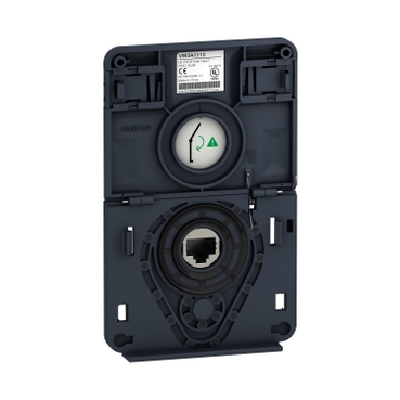
ATV930-ND 55kW;HD 45KW-480V;with braking unit;IP21
Mfr. Part No.:
ATV930D55N4
APT Stock No.:
SE-ATV930D55N4
Brand:
SCHNEIDER ELECTRIC
Currently Unavailable – Back Order Required
Subtotal (1 unit)**
(Exc. VAT)
(Inc. VAT)
Available For Back Order
Out of stock? No worries! You can back order this product.
To request a back order:
- Tap the Request Back Order button below
- Fill out the form with your Name, Email, Phone, and Company
Our team will review your request and contact you with availability and lead time.
* Delivery dates may change based on your quantity and address.
Shipping & Policy
Payment Methods:



Shipping Cost:
Contact the supplier about freight and estimated delivery time.
Secure payments:
Every payment you make on aptghana.com is protected by the platform.
Return policy
Enjoy peace of mind with our 7-day return policy for used items, provided they are returned in their original packaging.
Embedded power measurement and energy dashboard
Embedded process monitoring and control
Stop and Go function to reduce energy consumption
Asset monitoring and protection
Drift monitoring
Description

Shipping & Policy
Payment Methods:
Shipping Cost:
Contact the supplier about freight and estimated delivery time.
Secure payments:
Every payment you make on aptghana.com is protected by the platform.
Return policy
Enjoy peace of mind with our 7-day return policy for used items, provided they are returned in their original packaging.
Compatible products
Specifications
Dimensions Drawings
Front and Left View


Rear view

Mounting and Clearance

X1 | X2 | X3 |
|---|---|---|
≥ 100 mm (3.94 in.) | ≥ 100 mm (3.94 in.) | ≥ 10 mm (0.39 in.) |
Mount the device in a vertical position (±10°). This is required for cooling the device.
Do not mount the device close to heat sources.
Leave sufficient free space so that the air required for cooling purposes can circulate from the bottom to the top of the drive.
,

a ≥ = 110 mm (4.33 in.)


a ≥ = 110 mm (4.33 in.)
Connections and Schema
Connection diagrams conforming to standards EN 954-1 category 1 and IEC/EN 61508 capacity SIL1, stopping category 0 in accordance with standard IEC/EN 60204-1

(1) Line choke if used
(2) Use relay R1 set to operating state Fault to switch Off the product once an error is detected.
A1 : Drive
KM1 : Line Contactor
Q2, Q3 : Circuit breakers
S1, S2 : Pushbuttons
T1 : Transformer for control part
,
Connection diagrams conforming to standards EN 954-1 category 1 and IEC/EN 61508 capacity SIL1, stopping category 0 in accordance with standard IEC/EN 60204-1

(1) Line choke if used
(2) Use relay R1 set to operating state Fault to switch Off the product once an error is detected.
A1 : Drive
KM1 : Contactor
,

(1) Safe Torque Off
(2) Analog Output
(3) Digital Input
(4) Reference potentiometer
(5) Analog Input
(6) Digital Output
(7) 0-10 Vdc, x-20 mA
(8) 0-10 Vdc, -10 Vdc...+10 Vdc
R1A, R1B, R1C : Fault relay
R2A, R2C : Sequence relay
R3A, R3C : Sequence relay

It is possible to connect either 1 or 3 sensors on terminals AI1 or AI3
,
The switch is used to adapt the operation of the logic inputs to the technology of the programmable controller outputs.
Set the switch to Source (factory setting) if using PLC outputs with PNP transistors.
Set the switch to Ext if using PLC outputs with NPN transistors.


Performance Curves

 40 °C (104 °F) - Mounting type A, B and C
 50 °C (122 °F) - Mounting type A, B and C
 60 °C (140 °F) - Mounting type B and C
In : Nominal Drive Current
SF : Switching Frequency