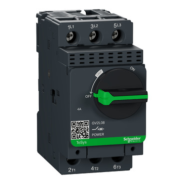

Motor circuit breaker, TeSys GV2, 3P, 4 A, magnetic, rotary handle, screw clamp terminals
Mfr. Part No.:
GV2L08
APT Stock No.:
SE-GV2L08
Brand:
SCHNEIDER ELECTRIC
In Stock: available
Need additional quantities?
Contact us for estimated lead timeSubtotal (1 unit)**
GHS 545.40
(Exc. VAT)
GHS 664.84
(Inc. VAT)
Available For Order
* Delivery dates may change based on your quantity and address.
Shipping & Policy
Payment Methods:


Shipping Cost:
Contact the supplier about freight and estimated delivery time.
Secure payments:
Every payment you make on aptghana.com is protected by the platform.
Return policy
Enjoy peace of mind with our 7-day return policy for used items, provided they are returned in their original packaging.
New modern look & feel of all machines
Wide range of GVs: Magnetic, thermal magnetic, different sizes (GV2,GV3,GV4)
Easier to install and operate with multi-standard screws
Sturdy and long-lasting power connection with EverLink terminals
Digital customer experience for technical documents
Description
TeSys GV motor circuit breaker, 3 poles (3P), 4A/690V, for 3-phase motor applications 1.1-1.5kW@400V. It provides a magnetic protection with a tripping level at 13xIn, high breaking capacity Icu 100kA@400V. Connection by screw clamp terminals. Start-stop control by rotary handle guaranteed for 100 000 cycles AC-3. To complete motor protection, use in association with a thermal overload relay LRD08 (to be ordered separately). Multi standards certified (IEC, UL, CSA, CCC, EAC, Marine),

Shipping & Policy
Payment Methods:
Shipping Cost:
Contact the supplier about freight and estimated delivery time.
Secure payments:
Every payment you make on aptghana.com is protected by the platform.
Return policy
Enjoy peace of mind with our 7-day return policy for used items, provided they are returned in their original packaging.
Compatible products
Accessories (1)
Add-ons (11)
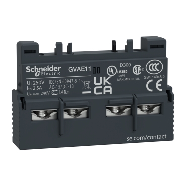
Auxiliaries (1)
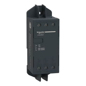
Interface connections (8)

Mounting (1)
Specifications
| Main | |
|---|---|
| Range | TeSys Deca |
| product name | TeSys GV2 |
| Product or component type | Motor circuit breaker |
| Device short name | GV2L |
| Device application | Motor protection |
| Trip unit technology | Magnetic |
| Complementary | |
|---|---|
| Poles description | 3P |
| Network type | AC |
| Utilisation category | Category A conforming to IEC 60947-2 AC-3 conforming to IEC 60947-4-1 AC-3e conforming to IEC 60947-4-1 |
| Network frequency | 50/60 Hz conforming to IEC 60947-2 |
| Motor power kW | 1.1 kW at 400/415 V AC 50/60 Hz 1.5 kW at 400/415 V AC 50/60 Hz 1.5 kW at 500 V AC 50/60 Hz 3 kW at 690 V AC 50/60 Hz |
| Breaking capacity | 100 kA Icu at 230/240 V AC 50/60 Hz conforming to IEC 60947-2 100 kA Icu at 400/415 V AC 50/60 Hz conforming to IEC 60947-2 100 kA Icu at 440 V AC 50/60 Hz conforming to IEC 60947-2 100 kA Icu at 500 V AC 50/60 Hz conforming to IEC 60947-2 4 kA Icu at 690 V AC 50/60 Hz conforming to IEC 60947-2 |
Performance Curves
Average Operating Times at 20 °C Related to Multiples of the Setting Current

Dynamic Stress
I peak = f (prospective Isc) at 1.05 Ue = 435 V

Dynamic Stress
I peak = f (prospective Isc) at 1.05 Ue = 435 V

Thermal Limit in kA2s in the Magnetic Operating Zone
Sum of I2dt = f (prospective Isc) at 1.05 Ue = 435 V

Thermal Limit in kA2s in the Magnetic Operating Zone
Sum of I2dt = f (prospective Isc) at 1.05 Ue = 435 V

Dimensions Drawings
Dimensions

X1 Electrical clearance = 40 mm for Ue ≤ 415 V, or 80 mm for Ue = 440 V, or 120 mm for Ue = 500 and 690 V.
X2 = 40 mm.
GVAD, AM, AN, AU, AS

GV2AK00

Mounting
On rail AM1 DE200, AM1 ED200 (35 x 15)

Panel mounted

On pre-slotted mounting plate AM1 PA

Adapter Plate GK2AF01

7.5 mm Height Compensation Plate GV1F03

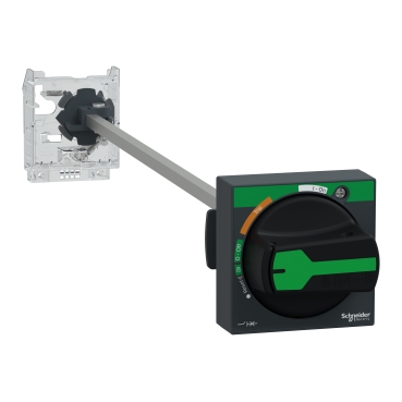
Mounting of External Operator GV2APN01, GV2APN02 or GV2APN04 for Motor Circuit Breakers GV2L

Door cut-out

Mounting of External Operator GVAPH02 for Motor Circuit Breakers GV2L

b | ||
|---|---|---|
Minimum | Maximum | |
GV2 APN●● + GV APH02 | 151 | 250 |
GV2 APN●● + GV APH02 + GV APK11 | 250 | 445 |
Door cut-out
GV2L and GV2LE
Sets of busbars GV2G445, GV2G454, GV2G472, with terminal block GV2G05

l | p | |
|---|---|---|
GV2G445 (4 x 45 mm) | 179 | 45 |
GV2G454 (4 x 54 mm) | 206 | 54 |
GV2G472 (4 x 72 mm) | 260 | 72 |
Number of tap-offs | a | |||
|---|---|---|---|---|
5 | 6 | 7 | 8 | |
GV2G445 | 224 | 269 | 314 | 359 |
GV2G454 | 260 | 314 | 368 | 422 |
GV2G472 | 332 | 404 | 476 | 548 |
Sets of Busbars for GV2L and GV2LE
Sets of busbars GV2G●●● with terminal block GV1G09

Sets of busbars GV2G245, GV2G254, GV2GR272

I | |
|---|---|
GV2G245 (2 x 45 mm) | 89 |
GV2G254 (2 x 54 mm) | 98 |
GV2G272 (2 x 72 mm) | 116 |
Set of busbars GV2G554

Sets of busbars GV2G345 and GV2G354

I | |
|---|---|
GV2G345 (3 x 45 mm) | 134 |
GV2G354 (3 x 54 mm) | 152 |
Connections and Schema
GV2L••