schneider-electric gv4le80n Picture
schneider-electric logo

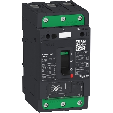
TeSys GV4 - magnetic circuit breaker - 80A 3P - with EverLink

Mfr. Part No.:

GV4LE80N

APT Stock No.:

SE-GV4LE80N

Brand:

Schneider Electric

Trip unit technology:
ElectronicMagnetic

Back Order

Subtotal (1 unit)**

GHS 4,647.97

(Exc. VAT)

GHS 5,665.88

(Inc. VAT)

Available For Order

* Delivery dates may change based on your quantity and address.

Shipping & Policy

Payment Methods:

Momo Page imagemastercardvise

Shipping Cost:

Contact the supplier about freight and estimated delivery time.

Secure payments:

Every payment you make on aptghana.com is protected by the platform.

Return policy

Enjoy peace of mind with our 7-day return policy for used items, provided they are returned in their original packaging.
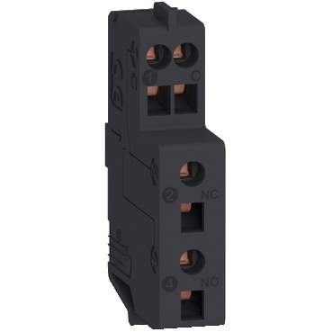
New modern look & feel of all machines

Wide range of GVs: Magnetic, thermal magnetic, different sizes (GV2,GV3,GV4)

Easier to install and operate with multi-standard screws

Safe and long-lasting power connection with EverLink terminals

Digital customer experience for technical documents

Description

TeSys GV motor circuit breaker, 3 poles (3P), 80A/690V, for protection of 3-phase motors 22-37kW@400V. It provides magnetic protection, breaking capacity Icu 50kA@400V, start-stop control by toggle, connection by Everlink BTR screw terminals. Magnetic protection adjustable by dial, setting range 6-14 In. It makes internal locations available for additional auxiliary contact blocks (OF, SD), and voltage trip units (MN, MX). To be used in association with a class 10 or 20 thermal overload relay to complete motor protection. Multi standards certified (IEC, CCC, EAC, Marine).

Compatible products

schneider-electric gv4le80n Picture

Add-ons (1)

Specifications

Main
Range of product
TeSys GV4
Range
TeSys Deca
Device short name
GV4L
product name
TeSys GV4
Product or component type
Motor circuit breaker
Device application
Motor protection
Trip unit technology
Magnetic
Electronic
Complementary
Poles description
3P
Utilisation category
Category A conforming to IEC 60947-2
AC-3 conforming to IEC 60947-4-1
Operating position
Any position
Motor power kW
37 kW at 400...415 V AC 50/60 Hz
45 kW at 500 V AC 50/60 Hz
55 kW at 500 V AC 50/60 Hz
22 kW at 400...415 V AC 50/60 Hz
30 kW at 500 V AC 50/60 Hz
37 kW at 660...690 V AC 50/60 Hz
45 kW at 660...690 V AC 50/60 Hz
55 kW at 660...690 V AC 50/60 Hz
30 kW at 400...415 V AC 50/60 Hz
37 kW at 500 V AC 50/60 Hz
Breaking capacity
100 kA Icu at 220...240 V AC 50/60 Hz conforming to IEC 60947-2
50 kA Icu at 380...415 V AC 50/60 Hz conforming to IEC 60947-2
50 kA Icu at 440 V AC 50/60 Hz conforming to IEC 60947-2
15 kA Icu at 525 V AC 50/60 Hz conforming to IEC 60947-2
8 kA Icu at 660...690 V AC 50/60 Hz conforming to IEC 60947-2
25 kA Icu at 500 V AC 50/60 Hz conforming to IEC 60947-2
Control type
Toggle

Performance Curves

Tripping Curves for GV4L and GV4LE Combined with Thermal Overload Relay LRD or LR9

Average Operating Times at 20 °C Related to Multiples of the Setting Current

GV4L02 and GV4LE02 to 12 with LRD05 to LRD14, GV4L80 and GV4LE80 with LRD3363


1
3 poles from cold state
2
2 poles from cold state
3
3 poles from hot state
4
6...14 Ir
A
Thermal overload relay protection zone
B
GV4L protection zone

GV4L25 and GV4LE25 with LRD 318, LRD325 GV4L50 AND GV4LE50 with LRD 332, LRD 340, LRD 350


1
3 poles from cold state
2
2 poles from cold state
3
3 poles from hot state
4
6...14 Ir
A
Thermal overload relay protection zone
B
GV4L protection zone

GV4L115 and GV4LE115 with Class 10 LR9F5367, LR9D5369 and Class 20 LR9D5567, LR9F5569


1
Cold state curve
2
Hot state curve
3
6...14 Ir

Current Limitation on Short-Circuit for GV4L, GV4LE (3-Phase 400/415 V)

Dynamic Stress

I peak = f (prospective Isc) at 1.05 Ue = 435 V


1
Maximum peak current
2
GV4L115
3
GV4L80
4
GV4L50
5
GV4L25
6
GV4L12
7
GV4L07
8
GV4L03
9
GV4L02

Current Limitation on Short-Circuit for GV4L, GV4LE + Thermal Overload Relay LRD or LR9 (3-Phase 400/415 V)

Dynamic Stress

I peak = f (prospective Isc) at 1.05 Ue = 435 V


1
Maximum peak current
2
GV4L115 + LR9D5367 or LR9F5367
3
GV4L80 + LRD3361
4
GV4L50 + LRD340
5
GV4L25 + LRD325
6
GV4L12 + LRD313
7
GV4L07 + LRD12
8
GV4L03 + LRD07
9
GV4L02 + LRD07

Thermal Limit on Short-Circuit for GV4L, GV4LE

Thermal Limit in A2s

Sum of I2dt = f (prospective Isc) at 1.05 Ue = 435 V


1
GV4L115
2
GV4L80
3
GV4L50
4
GV4L25
5
GV4L12
6
GV4L07
7
GV4L03
8
GV4L02

Current Limitation on Short-Circuit for GV4L, GV4LE + Thermal Overload Relay LRD or LR9

Thermal Limit in kA in the Magnetic Operating Zone

Sum of I2dt = f (prospective Isc) at 1.05 Ue = 435 V


1
GV4L115 + LR9D5367 or LR9F5367
2
GV4L80 + LRD3361
3
GV4L50 + LRD340
4
GV4L25 + LRD325
5
GV4L12 + LRD313
6
GV4L07+ LRD12
7
GV4L03+ LRD07
8
GV4L02 + LRD07


Dimensions Drawings

GV4 with Toggle: GV4LE, GV4PE, GV4PEM

With EverLink® Connector


With Crimp Lug Connector


(1)
Interphases barriers
(2)
Long terminal shield

GV4 with Rotary Handle: GV4L, GV4P, or GV4LE, GV4PE, GV4PEM with GV4ADN01, GV4ADN02 Direct Mounting Rotary Handle

Dimensions


GV4L, GV4P, GV4LE, GV4PE, GV4PEM

Panel Mounting with M4 Screws


Door Cut-Out for Rotary Handle


Minimum Safety Clearance


Toggle-type, rotary handle-type: identical clearance values.

Safety Clearance (mm)

Painted Sheet Metal

Bare Sheet Metal

A

B

C

A

B

C

No accessory

30

0

0

40

0

5

Interphase barriers

0

0

0

0

0

5

Long terminal shield

0

0

0

0

0

5


Connections and Schema

Magnetic Motor Circuit Breakers

GV4L, GV4LE


help mobile view

Need more information?

Check with our technical team!

Contact Us