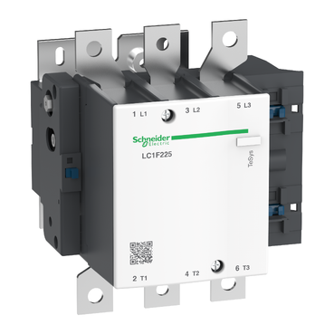

TeSys F contactor - 3P (3 NO) - AC-3 - <= 440 V 225 A - coil 230 V AC
Mfr. Part No.:
LC1F225P7
APT Stock No.:
SE-LC1F225P7
Brand:
Schneider Electric
Back Order
Need more stock?
Contact us for Est. Lead TimeSubtotal (1 unit)**
GHS 9,082.59
(Exc. VAT)
GHS 11,071.68
(Inc. VAT)
Available For Order
* Delivery dates may change based on your quantity and address.
Shipping & Policy
Payment Methods:


Shipping Cost:
Contact the supplier about freight and estimated delivery time.
Secure payments:
Every payment you make on aptghana.com is protected by the platform.
Return policy
Enjoy peace of mind with our 7-day return policy for used items, provided they are returned in their original packaging.
Description
TeSys F contactor, 3 poles (3NO), 225A/690V AC-3, for motor applications up to 110kW@400V. It provides a low sealed consumption 230V 40-400Hz AC coil, bolt terminals for bars or cables with lugs. For high operating rates until 2400 cycles/hour and environments until 55°C, it procures high reliability and durability. It makes installation and maintenance easy thanks to its drawer-mounted coil and a large choice of add-on blocks and accessories (to be ordered separately). Multi standards certified (IEC, UL, CSA, CCC, EAC, Marine), Green Premium compliant (RoHS/REACh).

Shipping & Policy
Payment Methods:
Shipping Cost:
Contact the supplier about freight and estimated delivery time.
Secure payments:
Every payment you make on aptghana.com is protected by the platform.
Return policy
Enjoy peace of mind with our 7-day return policy for used items, provided they are returned in their original packaging.
Specifications
| Main | |
|---|---|
| Range | TeSys |
| Range of product | TeSys F |
| Product or component type | Contactor |
| Device short name | LC1F |
| Contactor application | Motor control Resistive load |
| Utilisation category | AC-3 AC-1 AC-4 |
| Poles description | 3P |
| [Ue] rated operational voltage | <= 460 V DC <= 690 V AC 50/60 Hz |
| [Uc] control circuit voltage | 230 V AC 40...400 Hz |
| [Ie] rated operational current | 315 A (at <40 °C) at <= 440 V AC-1 225 A (at <55 °C) at <= 440 V AC-3 |
| Complementary | |
|---|---|
| [Uimp] rated impulse withstand voltage | 8 kV |
| [Ith] conventional free air thermal current | 315 A (at 40 °C) |
| Rated breaking capacity | 1800 A conforming to IEC 60947-4-1 |
| [Icw] rated short-time withstand current | 1800 A 40 °C - 10 s 1000 A 40 °C - 30 s 850 A 40 °C - 1 min 560 A 40 °C - 3 min 440 A 40 °C - 10 min |
| Associated fuse rating | 315 A gG at <= 440 V 250 A aM at <= 440 V |
| Average impedance | 0.32 mOhm - Ith 315 A 50 Hz |
Dimensions Drawings

X1 (mm) = Minimum electrical clearance according to operating voltage and breaking capacity.
LC1 | 200...500 V | 600...1000 V |
|---|---|---|
F115, F150 | 10 | 15 |
F185 | 10 | 15 |
F225, F265 | 10 | 15 |
F330 | 10 | 15 |
LC1 | a | b | b1 | b2 | c | f | G | G1 | J | J1 | L | M | P | Q | Q1 | S | S1 | Y | Z | |
|---|---|---|---|---|---|---|---|---|---|---|---|---|---|---|---|---|---|---|---|---|
F115 | 3P | 163.5 | 162 | 137 | 265 | 171 | 131 | 106 | 80 | 106 | 120 | 107 | 147 | 37 | 29.5 | 60 | 20 | 26 | 44 | 13.5 |
4P | 200.5 | 162 | 137 | 265 | 171 | 131 | 143 | 80 | 106 | 120 | 107 | 147 | 37 | 29.5 | 60 | 20 | 26 | 44 | 13.5 | |
F150 | 3P | 163.5 | 170 | 137 | 301 | 171 | 131 | 106 | 80 | 106 | 120 | 107 | 150 | 40 | 26 | 57.5 | 20 | 34 | 44 | 13.5 |
4P | 200.5 | 170 | 137 | 301 | 171 | 131 | 143 | 80 | 106 | 120 | 107 | 150 | 40 | 26 | 55.5 | 20 | 34 | 44 | 13.5 | |
F185 | 3P | 168.5 | 174 | 137 | 305 | 181 | 130 | 111 | 80 | 106 | 120 | 113.5 | 154 | 40 | 29 | 59.5 | 20 | 34 | 44 | 13.5 |
4P | 208.5 | 174 | 137 | 305 | 181 | 130 | 151 | 80 | 106 | 120 | 113.5 | 154 | 40 | 29 | 59.5 | 20 | 34 | 44 | 13.5 | |
F225 | 3P | 168.5 | 197 | 137 | 364 | 181 | 130 | 111 | 80 | 106 | 120 | 113.5 | 172 | 48 | 21 | 51.5 | 25 | 44.5 | 44 | 13.5 |
4P | 208.5 | 197 | 137 | 364 | 181 | 130 | 151 | 80 | 106 | 120 | 113.5 | 172 | 48 | 17 | 47.5 | 25 | 44.5 | 44 | 13.5 | |
F265 | 3P | 201.5 | 203 | 145 | 375 | 213 | 147 | 142 | 96 | 106 | 120 | 141 | 178 | 48 | 39 | 66.5 | 25 | 44.5 | 38 | 21.5 |
4P | 244.5 | 203 | 145 | 375 | 213 | 147 | 190 | 96 | 106 | 120 | 141 | 178 | 48 | 34 | 66.5 | 25 | 44.5 | 38 | 16.5 | |
F330 | 3P | 213 | 206 | 145 | 375 | 219 | 147 | 154.5 | 96 | 106 | 120 | 145 | 181 | 48 | 43 | 74 | 25 | 44.5 | 38 | 20.5 |
4P | 261 | 206 | 145 | 375 | 219 | 147 | 202.5 | 96 | 106 | 120 | 145 | 181 | 48 | 43 | 74 | 25 | 44.5 | 38 | 20.5 | |
NOTE: For customer assembly, with mechanical interlock (MI) LA9 F, fixing recommended on AM1 EC uprights (please consult your Regional Sales Office). 2 x LC1 identical or different ratings (LC1 F115 to F630 and F800).
Assembly A

Assembly A(7) - Mechanical interlock reference
G3 3P | G3 4P | H min. | H max. | H1 min. | H1 max. | J1 3P | J1 4P | |
|---|---|---|---|---|---|---|---|---|
LA9 FF4F | 0 | 0 | 200 | 310 | 80 | 190 | 137 | 155.5 |
LA9 FG4F | 3 | 4 | 210 | 300 | 90 | 180 | 139.5 | 159.5 |
LA9 FG4G | 0 | 0 | 220 | 310 | 100 | 190 | 139.5 | 159.5 |
J2 3P | J2 4P | J3 3P | J3 4P | J4 3P | J4 4P | |
|---|---|---|---|---|---|---|
LA9 FF4F | 137 | 155.5 | 48.5 | 67 | 48.5 | 67 |
LA9 FG4F | 137 | 155.5 | 53 | 73 | 54 | 69 |
LA9 FG4G | 139.5 | 159.5 | 53 | 73 | 53 | 73 |
Assembly B

Assembly B(7) - Mechanical interlock reference
G1 3P | G1 4P | G3 3P | G3 4P | G5 3P | G5 4P | H min. | H max. | |
|---|---|---|---|---|---|---|---|---|
LA9 FH4F | 96 | 96 | 21 | 27 | 60 | 83 | 240 | 380 |
LA9 FJ4F | 80 | 80 | 45 | 26 | 83 | 83 | 250 | 380 |
LA9 FK4F | 80 | 140 | 45 | 26 | 83 | 83 | 270 | 380 |
LA9 FL4F | 180 | 240 | 35 | 17 | 74 | 74 | 310 | 380 |
LA9 FH4G | 96 | 96 | 19 | 23 | 60 | 83 | 250 | 380 |
LA9 FJ4G | 80 | 80 | 42 | 22 | 83 | 83 | 250 | 380 |
LA9 FK4G | 80 | 140 | 42 | 22 | 83 | 83 | 270 | 380 |
LA9 FL4G | 180 | 240 | 33 | 13 | 74 | 74 | 310 | 380 |
H1 min. | H1 max. | J1 3P | J1 4P | J2 3P | J2 4P | J4 3P | J4 4P | |
|---|---|---|---|---|---|---|---|---|
LA9 FH4F | 110 | 250 | 157.5 | 181.5 | 137 | 155.5 | 48.5 | 67 |
LA9 FJ4F | 80 | 210 | 144.5 | 192.5 | 137 | 155.5 | 48.5 | 67 |
LA9 FK4F | 100 | 210 | 164.5 | 219.5 | 137 | 155.5 | 48.5 | 67 |
LA9 FL4F | 140 | 210 | 248.5 | 328.5 | 137 | 155.5 | 48.5 | 67 |
LA9 FH4G | 120 | 250 | 157.5 | 181.5 | 139.5 | 159.5 | 53 | 73 |
LA9 FJ4G | 90 | 220 | 144.5 | 192.5 | 139.5 | 159.5 | 53 | 73 |
LA9 FK4G | 110 | 220 | 164.5 | 219.5 | 139.5 | 159.5 | 53 | 73 |
LA9 FL4G | 150 | 220 | 248.5 | 328.5 | 139.5 | 159.5 | 53 | 73 |
Assembly C


Assembly C(7)
G1 3P | G1 4P | G2 3P | G2 4P | G3 3P | G3 4P | G4 3P | G4 4P | G5 3P | G5 4P | |
|---|---|---|---|---|---|---|---|---|---|---|
LA9 FH4H | 96 | 96 | 96 | 96 | 0 | 0 | 60 | 83 | 60 | 83 |
LA9 FJ4H | 80 | 80 | 96 | 96 | 23 | 0 | 60 | 83 | 83 | 83 |
LA9 FK4H | 80 | 140 | 96 | 96 | 23 | 0 | 60 | 83 | 83 | 83 |
LA9 FL4H | 180 | 240 | 96 | 96 | 14 | 9(8) | 60 | 83 | 74 | 74 |
LA9 FJ4J | 80 | 80 | 80 | 80 | 0 | 0 | 83 | 83 | 83 | 83 |
LA9 FK4J | 80 | 140 | 80 | 80 | 0 | 0 | 83 | 83 | 83 | 83 |
LA9 FL4J | 180 | 240 | 80 | 80 | 9(8) | 9(8) | 83 | 83 | 74 | 74 |
LA9 FK4K | 80 | 140 | 80 | 140 | 0 | 0 | 83 | 83 | 83 | 83 |
LA9 FL4K | 180 | 240 | 80 | 140 | 9(8) | 9(8) | 83 | 83 | 74 | 74 |
LA9 FL4L | 180 | 240 | 180 | 240 | 0 | 0 | 74 | 74 | 74 | 74 |
H min. | H max. | H1 min. | H1 max. | J1 3P | J1 4P | J2 3P | J2 4P | |
|---|---|---|---|---|---|---|---|---|
LA9 FH4H | 250 | 380 | 130 | 260 | 157.5 | 181.5 | 157.5 | 181.5 |
LA9 FJ4H | 260 | 380 | 110 | 230 | 144.5 | 192.5 | 157.5 | 181.5 |
LA9 FK4H | 280 | 380 | 130 | 230 | 164.5 | 219.5 | 157.5 | 181.5 |
LA9 FL4H | 330 | 380 | 170 | 220 | 248.5 | 328.5 | 157.5 | 181.5 |
LA9 FJ4J | 260 | 380 | 60 | 200 | 144.5 | 192.5 | 144.5 | 192.5 |
LA9 FK4J | 280 | 380 | 100 | 200 | 164.5 | 219.5 | 144.5 | 192.5 |
LA9 FL4J | 325 | 380 | 140 | 195 | 248.5 | 329.5 | 144.5 | 192.5 |
LA9 FK4K | 300 | 380 | 120 | 200 | 164.5 | 329.5 | 164.5 | 219.5 |
LA9 FL4K | 345 | 380 | 160 | 195 | 248.5 | 328.5 | 164.5 | 219.5 |
LA9 FL4L | 380 | 380 | 200 | 200 | 248.5 | 328.5 | 248.5 | 328.5 |
Connections and Schema

LC1 F115 to F630, F1250(coil LX1 F  )
)

LC1 F115 to F630 , F1250 (coil LX4 F  )
)
LC1 F115 to F265 (coil LX9 F )
LC1 F800 (coil LX8 F / )