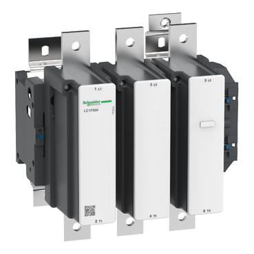

TeSys F contactor - 3P (3 NO) - AC-3 - <= 440 V 800 A - coil 400 V DC
Mfr. Part No.:
LC1F800QW
APT Stock No.:
SE-LC1F800QW
Brand:
Schneider Electric
Back Order
Need more stock?
Contact us for Est. Lead TimeSubtotal (1 unit)**
GHS 45,803.44
(Exc. VAT)
GHS 55,834.39
(Inc. VAT)
Available For Order
* Delivery dates may change based on your quantity and address.
Shipping & Policy
Payment Methods:


Shipping Cost:
Contact the supplier about freight and estimated delivery time.
Secure payments:
Every payment you make on aptghana.com is protected by the platform.
Return policy
Enjoy peace of mind with our 7-day return policy for used items, provided they are returned in their original packaging.

Shipping & Policy
Payment Methods:
Shipping Cost:
Contact the supplier about freight and estimated delivery time.
Secure payments:
Every payment you make on aptghana.com is protected by the platform.
Return policy
Enjoy peace of mind with our 7-day return policy for used items, provided they are returned in their original packaging.
Specifications
| Main | |
|---|---|
| Range | TeSys |
| Range of product | TeSys F |
| Product or component type | Contactor |
| Device short name | LC1F |
| Contactor application | Resistive load Motor control |
| Utilisation category | AC-3 AC-1 AC-4 |
| Poles description | 3P |
| [Ue] rated operational voltage | <= 1000 V AC 50/60 Hz <= 460 V DC |
| [Uc] control circuit voltage | 400 V DC 380...415 V AC 40...400 Hz |
| [Ie] rated operational current | 1000 A (at <40 °C) at <= 440 V AC AC-1 800 A (at <55 °C) at <= 440 V AC AC-3 |
| Complementary | |
|---|---|
| [Uimp] rated impulse withstand voltage | 8 kV |
| [Ith] conventional free air thermal current | 1000 A (at 40 °C) |
| Rated breaking capacity | 6400 A conforming to IEC 60947-4-1 |
| [Icw] rated short-time withstand current | 5500 A 40 °C - 10 s 4600 A 40 °C - 30 s 3600 A 40 °C - 1 min 2600 A 40 °C - 3 min 1700 A 40 °C - 10 min |
| Associated fuse rating | 1000 A gG at <= 440 V 800 A aM at <= 440 V |
| Average impedance | 0.12 mOhm - Ith 1000 A 50 Hz |
Dimensions Drawings


NOTE: X1 (mm) = Minimum electrical clearance according to operating voltage and breaking capacity.
LC1 | a | G supplied | G min. | G max. | J1 | Q | Q1 | |
|---|---|---|---|---|---|---|---|---|
F630 | 2P | 309 | 180 | 100 | 195 | 68.5 | 102 | 127 |
F630, F800 | 3P | 309 | 180 | 100 | 195 | 68.5 | 60 | 89 |
F630 | 4P | 389 | 240 | 150 | 275 | 88.5 | 60 | 89 |
Voltage | 200…500 V | 690…1000 V | 200…690 V | 1000 V |
|---|---|---|---|---|
LC1 F630 | 20 | 30 | – | – |
LC1 F800 | – | – | 10 | 20 |
NOTE: For customer assembly, with mechanical interlock (MI) LA9 F, fixing recommended on AM1 EC uprights (please consult your Regional Sales Office). 2 x LC1 identical or different ratings (LC1 F115 to F630 and F800).
Assembly A

Assembly A(7) - Mechanical interlock reference
G3 3P | G3 4P | H min. | H max. | H1 min. | H1 max. | J1 3P | J1 4P | |
|---|---|---|---|---|---|---|---|---|
LA9 FF4F | 0 | 0 | 200 | 310 | 80 | 190 | 137 | 155.5 |
LA9 FG4F | 3 | 4 | 210 | 300 | 90 | 180 | 139.5 | 159.5 |
LA9 FG4G | 0 | 0 | 220 | 310 | 100 | 190 | 139.5 | 159.5 |
J2 3P | J2 4P | J3 3P | J3 4P | J4 3P | J4 4P | |
|---|---|---|---|---|---|---|
LA9 FF4F | 137 | 155.5 | 48.5 | 67 | 48.5 | 67 |
LA9 FG4F | 137 | 155.5 | 53 | 73 | 54 | 69 |
LA9 FG4G | 139.5 | 159.5 | 53 | 73 | 53 | 73 |
Assembly B

Assembly B(7) - Mechanical interlock reference
G1 3P | G1 4P | G3 3P | G3 4P | G5 3P | G5 4P | H min. | H max. | |
|---|---|---|---|---|---|---|---|---|
LA9 FH4F | 96 | 96 | 21 | 27 | 60 | 83 | 240 | 380 |
LA9 FJ4F | 80 | 80 | 45 | 26 | 83 | 83 | 250 | 380 |
LA9 FK4F | 80 | 140 | 45 | 26 | 83 | 83 | 270 | 380 |
LA9 FL4F | 180 | 240 | 35 | 17 | 74 | 74 | 310 | 380 |
LA9 FH4G | 96 | 96 | 19 | 23 | 60 | 83 | 250 | 380 |
LA9 FJ4G | 80 | 80 | 42 | 22 | 83 | 83 | 250 | 380 |
LA9 FK4G | 80 | 140 | 42 | 22 | 83 | 83 | 270 | 380 |
LA9 FL4G | 180 | 240 | 33 | 13 | 74 | 74 | 310 | 380 |
H1 min. | H1 max. | J1 3P | J1 4P | J2 3P | J2 4P | J4 3P | J4 4P | |
|---|---|---|---|---|---|---|---|---|
LA9 FH4F | 110 | 250 | 157.5 | 181.5 | 137 | 155.5 | 48.5 | 67 |
LA9 FJ4F | 80 | 210 | 144.5 | 192.5 | 137 | 155.5 | 48.5 | 67 |
LA9 FK4F | 100 | 210 | 164.5 | 219.5 | 137 | 155.5 | 48.5 | 67 |
LA9 FL4F | 140 | 210 | 248.5 | 328.5 | 137 | 155.5 | 48.5 | 67 |
LA9 FH4G | 120 | 250 | 157.5 | 181.5 | 139.5 | 159.5 | 53 | 73 |
LA9 FJ4G | 90 | 220 | 144.5 | 192.5 | 139.5 | 159.5 | 53 | 73 |
LA9 FK4G | 110 | 220 | 164.5 | 219.5 | 139.5 | 159.5 | 53 | 73 |
LA9 FL4G | 150 | 220 | 248.5 | 328.5 | 139.5 | 159.5 | 53 | 73 |
Assembly C


Assembly C(7)
G1 3P | G1 4P | G2 3P | G2 4P | G3 3P | G3 4P | G4 3P | G4 4P | G5 3P | G5 4P | |
|---|---|---|---|---|---|---|---|---|---|---|
LA9 FH4H | 96 | 96 | 96 | 96 | 0 | 0 | 60 | 83 | 60 | 83 |
LA9 FJ4H | 80 | 80 | 96 | 96 | 23 | 0 | 60 | 83 | 83 | 83 |
LA9 FK4H | 80 | 140 | 96 | 96 | 23 | 0 | 60 | 83 | 83 | 83 |
LA9 FL4H | 180 | 240 | 96 | 96 | 14 | 9(8) | 60 | 83 | 74 | 74 |
LA9 FJ4J | 80 | 80 | 80 | 80 | 0 | 0 | 83 | 83 | 83 | 83 |
LA9 FK4J | 80 | 140 | 80 | 80 | 0 | 0 | 83 | 83 | 83 | 83 |
LA9 FL4J | 180 | 240 | 80 | 80 | 9(8) | 9(8) | 83 | 83 | 74 | 74 |
LA9 FK4K | 80 | 140 | 80 | 140 | 0 | 0 | 83 | 83 | 83 | 83 |
LA9 FL4K | 180 | 240 | 80 | 140 | 9(8) | 9(8) | 83 | 83 | 74 | 74 |
LA9 FL4L | 180 | 240 | 180 | 240 | 0 | 0 | 74 | 74 | 74 | 74 |
H min. | H max. | H1 min. | H1 max. | J1 3P | J1 4P | J2 3P | J2 4P | |
|---|---|---|---|---|---|---|---|---|
LA9 FH4H | 250 | 380 | 130 | 260 | 157.5 | 181.5 | 157.5 | 181.5 |
LA9 FJ4H | 260 | 380 | 110 | 230 | 144.5 | 192.5 | 157.5 | 181.5 |
LA9 FK4H | 280 | 380 | 130 | 230 | 164.5 | 219.5 | 157.5 | 181.5 |
LA9 FL4H | 330 | 380 | 170 | 220 | 248.5 | 328.5 | 157.5 | 181.5 |
LA9 FJ4J | 260 | 380 | 60 | 200 | 144.5 | 192.5 | 144.5 | 192.5 |
LA9 FK4J | 280 | 380 | 100 | 200 | 164.5 | 219.5 | 144.5 | 192.5 |
LA9 FL4J | 325 | 380 | 140 | 195 | 248.5 | 329.5 | 144.5 | 192.5 |
LA9 FK4K | 300 | 380 | 120 | 200 | 164.5 | 329.5 | 164.5 | 219.5 |
LA9 FL4K | 345 | 380 | 160 | 195 | 248.5 | 328.5 | 164.5 | 219.5 |
LA9 FL4L | 380 | 380 | 200 | 200 | 248.5 | 328.5 | 248.5 | 328.5 |
Connections and Schema

LC1 F115 to F630, F1250(coil LX1 F  )
)

LC1 F115 to F630 , F1250 (coil LX4 F  )
)
LC1 F115 to F265 (coil LX9 F )
LC1 F800 (coil LX8 F / )