
controller M221 24 IO relay Ethernet
Mfr. Part No.:
TM221CE24R
APT Stock No.:
SE-TM221CE24R
Brand:
SCHNEIDER ELECTRIC
In Stock: available
Need additional quantities?
Contact us for estimated lead timeSubtotal (1 unit)**
GHS 10,867.65
(Exc. VAT)
GHS 13,247.67
(Inc. VAT)
Available For Order
* Delivery dates may change based on your quantity and address.
Shipping & Policy
Payment Methods:


Shipping Cost:
Contact the supplier about freight and estimated delivery time.
Secure payments:
Every payment you make on aptghana.com is protected by the platform.
Return policy
Enjoy peace of mind with our 7-day return policy for used items, provided they are returned in their original packaging.
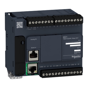
SD card and USB port
2 analog inputs and a broad choice of I/Os
Run/stop switch and cartridge extension
Ethernet and serial line ports
M221 controllers can connect to Modicon TM3 expansion modules for local, remote or distributed I/O configurations
Description
This product is part of the Modicon M221 range, an offer of programmable logic controllers for hardwired architectures. This logic controller provides 14 discrete inputs and 10 relay ethernet outputs with 10bit input resolution, normally opened relay output. It is a Modicon logic controller with a rated supply voltage of 100V to 240V AC, an output voltage of 5V to 125V DC, 5V to 250V AC and an output current of 2A with sink or source input logic. This product requires minimal installation and offers tremendous versatility. Integrated connections are USB port with mini B USB 2.0 connector, non isolated serial link serial 1 with RJ45 connector and RS232/RS485 interface and ethernet with RJ45 connector. It is a Modicon M221 controller with a network frequency of 50/60Hz, 256KB for internal variables RAM, user application and data RAM, a built-in flash memory of 256KB and a SD card memory capacity of 2GB. It is an IP20 rated product. Its dimensions are 110mm (Width) x 70mm (Depth) x 90mm (Height). It weighs 0.395kg. This product is certified by CE, IACS E10, RCM, ABS, LR, DNV-GL, CSA, EAC and CULus. It meets EN/IEC 60664-1, EN/IEC 61131-2 and EN/IEC 61010-2-201 standards. It supports DIN rail mount. Achieve benchmark performance while increasing profitability with the Modicon M221 through intuitive machine programming with SoMachine Basic, ready-to-use applications and function blocks

Shipping & Policy
Payment Methods:
Shipping Cost:
Contact the supplier about freight and estimated delivery time.
Secure payments:
Every payment you make on aptghana.com is protected by the platform.
Return policy
Enjoy peace of mind with our 7-day return policy for used items, provided they are returned in their original packaging.
Specifications
| Main | |
|---|---|
| Range of product | Modicon M221 |
| Product or component type | Logic controller |
| [Us] rated supply voltage | 100...240 V AC |
| Discrete input number | 14, discrete input conforming to IEC 61131-2 Type 1 |
| Analogue input number | 2 at 0...10 V |
| Discrete output type | Relay normally open |
| Discrete output number | 10 relay |
| Discrete output voltage | 5...125 V DC 5...250 V AC |
| Discrete output current | 2 A |
| Complementary | |
|---|---|
| Discrete I/O number | 24 |
| Maximum number of I/O expansion module | 7 (local I/O-Architecture) 14 (remote I/O-Architecture) |
| Supply voltage limits | 85…264 V |
| Network frequency | 50/60 Hz |
| Inrush current | 40 A |
| Maximum power consumption in VA | 58 VA at 100...240 V with max number of I/O expansion module 35 VA at 100...240 V without I/O expansion module |
Dimensions Drawings

Mounting and Clearance

,


,


,

Connections and Schema


,


,


Pin | Wire Color |
|---|---|
0 V | Black |
AN1 | Red |
0 V | Black |
AN0 | Red |
,

Pin N° | Signal |
|---|---|
1 | TD+ |
2 | TD- |
3 | RD+ |
4 | - |
5 | - |
6 | RD- |
7 | - |
8 | - |

,

,

SL1
N ° | RS 232 | RS 485 |
|---|---|---|
1 | RxD | N.C. |
2 | TxD | N.C. |
3 | RTS | N.C. |
4 | N.C. | D1 |
5 | N.C. | D0 |
6 | CTS | N.C. |
7 | N.C*. | 5 Vdc |
8 | Common | Common |
N.C.: not connected
* : 5 Vdc delivered by the controller. Do not connect.

Performance Curves