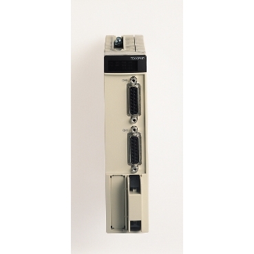
4 channels counter modules - 40 kHz - 36 mA at 24 V DC, 330 mA at 5 V DC
Mfr. Part No.:
TSXCTY4A
APT Stock No.:
SE-TSXCTY4A
Brand:
SCHNEIDER ELECTRIC
Currently Unavailable – Back Order Required
Available For Back Order
Out of stock? No worries! You can back order this product.
To request a back order:
- Tap the Request Back Order button below
- Fill out the form with your Name, Email, Phone, and Company
Our team will review your request and contact you with availability and lead time.
* Delivery dates may change based on your quantity and address.
Shipping & Policy
Payment Methods:


Shipping Cost:
Contact the supplier about freight and estimated delivery time.
Secure payments:
Every payment you make on aptghana.com is protected by the platform.
Return policy
Enjoy peace of mind with our 7-day return policy for used items, provided they are returned in their original packaging.
The counter module consists of 4 channels
Positive logic DC inputs for auxillary outputs
Thermal tripping via program or automatic current limiter
Overvoltage protection via zener diode.

Shipping & Policy
Payment Methods:
Shipping Cost:
Contact the supplier about freight and estimated delivery time.
Secure payments:
Every payment you make on aptghana.com is protected by the platform.
Return policy
Enjoy peace of mind with our 7-day return policy for used items, provided they are returned in their original packaging.
Specifications
Dimensions Drawings

(1) With screw terminal block modules.
(2) Maximum depth for all types of modules and their associated connectors.
Connections and Schema

5 Vdc signal | Pins |
|---|---|
+ IA input | 1 |
- IA input | 2 |
+ IB input | 10 |
- IB input | 11 |
+ IZ input | 4 |
- IZ input | 5 |
Encoder power supply: | |
+5 Vdc | 15 |
-0 Vdc | 8 |
Encoder power supply feedback | 13 |
10…30 Vdc signals | Pins |
|---|---|
+ IA input | 9 |
- IA input | 2 |
+ IB input | 3 |
- IB input | 11 |
+ IZ input | 12 |
- IZ input | 5 |
Encoder power supply: | |
+10…30 Vdc | 7 |
-0 Vdc | 8 |
Encoder power supply feedback | 13 |
,

24 Vdc signals | Pins |
|---|---|
Channel 0 (channel 2) auxiliary input: | |
Preset IPres0/2 | 5 |
Confirmation IVal0/2 | 6 |
Capture ICapt0/2 | 7 |
Channel 1 (channel 3) auxiliary input: | |
Preset IPres1/3 | 9 |
Confirmation IVal1/3 | 10 |
Capture ICapt1/3 | 11 |
Channel 0 (channel 2) reflex output: | |
Output Q0 | 13 |
Output Q1 | 14 |
Channel 1 reflex output: | |
Output Q0 | 15 |
Output Q1 | 16 |
Power Supplies | Pins |
|---|---|
Encoder power supply: | |
+5 Vdc | 1 |
- 0 Vdc | 2 |
+10...30 Vdc | 3 |
Sensor power supply: | |
+24 Vdc | 17 or 19 |
-0 Vdc | 18 or 20 |