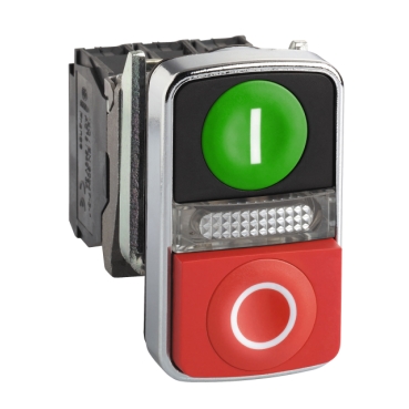
Illuminated double-headed push button, metal, Ø22, 1 green flush I + 1 pilot light + 1 red projecting O, 1 NO + 1 NC
Mfr. Part No.:
XB4BW73731B5
APT Stock No.:
SE-XB4BW73731B5
Brand:
SCHNEIDER ELECTRIC
In Stock: available
Need additional quantities?
Contact us for estimated lead timeSubtotal (1 unit)**
GHS 367.65
(Exc. VAT)
GHS 448.17
(Inc. VAT)
Available For Order
* Delivery dates may change based on your quantity and address.
Shipping & Policy
Payment Methods:


Shipping Cost:
Contact the supplier about freight and estimated delivery time.
Secure payments:
Every payment you make on aptghana.com is protected by the platform.
Return policy
Enjoy peace of mind with our 7-day return policy for used items, provided they are returned in their original packaging.
Quick and easy assembly and disassembly
Robustness to withstand harsh environments
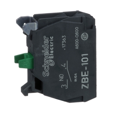
Various types of connection: screw clamp, connector, Faston connector or spring terminal
Excellent mechanical connection with operator head
A wide choice of contact blocks for general purposes or specific applications (low current, standard)
Description

Shipping & Policy
Payment Methods:
Shipping Cost:
Contact the supplier about freight and estimated delivery time.
Secure payments:
Every payment you make on aptghana.com is protected by the platform.
Return policy
Enjoy peace of mind with our 7-day return policy for used items, provided they are returned in their original packaging.
Compatible products
Specifications
Dimensions Drawings

Mounting and Clearance
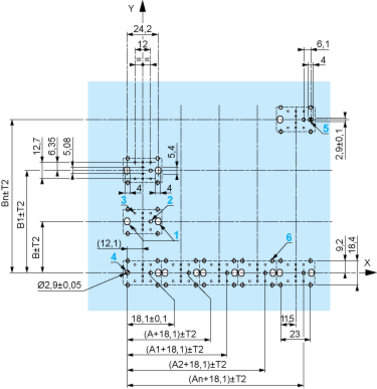
Connection by Screw Clamp Terminals or Plug-in Connectors or on Printed Circuit Board | Connection by Faston Connectors |
|
|
(1) Diameter on finished panel or support (2) 40 mm min. / 1.57 in. min. (3) 30 mm min. / 1.18 in. min. (4) Ø 22.5 mm / 0.89 in. recommended (Ø 22.3 mm 0+0.4 / 0.88 in. 0+0.016) (5) 45 mm min. / 1.78 in. min. (6) 32 mm min. / 1.26 in. min. | |


,
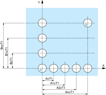
A: 30 mm min. / 1.18 in. min.
B: 40 mm min. / 1.57 in. min.
Dimensions in mm
A: 30 mm min.
B: 40 mm min.
Dimensions in in.

A: 1.18 in. min.
B: 1.57 in. min.
The cumulative tolerance must not exceed 0.3 mm / 0.012 in: T1 + T2 = 0.3 mm max.
Minimum thickness of circuit board: 1.6 mm / 0.06 in.
Cut-out diameter: 22.4 mm ± 0.1 / 0.88 in. ± 0.004
Orientation of body/fixing collar ZB4 BZ009: ± 2°30' (excluding cut-outs marked a and b).
Tightening torque of screws ZBZ 006: 0.6 N.m (5.3 lbf.in) max.
Allow for one ZB4 BZ079 fixing collar/pillar and its fixing screws:
every 90 mm / 3.54 in. horizontally (X), and 120 mm / 4.72 in. vertically (Y).
with each selector switch head (ZB4 BD•, ZB4 BJ•, ZB4 BG•).
The fixing centers marked a and b are diagonally opposed and must align with those marked 4 and 5.

(1) Panel
(2) Printed circuit board
1 2 elongated holes for ZBZ 006 screw access
2 1 hole Ø 2.4 mm ± 0.05 / 0.09 in. ± 0.002 for centring adapter ZBZ 01•
3 8 × Ø 1.2 mm / 0.05 in. holes
4 1 hole Ø 2.9 mm ± 0.05 / 0.11 in. ± 0.002, for aligning the printed circuit board (with cut-out marked a)
5 1 elongated hole for aligning the printed circuit board (with cut-out marked b)
6 4 holes Ø 2.4 mm / 0.09 in. for clipping in adapter ZBZ 01•
Dimensions An + 18.1 relate to the Ø 2.4 mm ± 0.05 / 0.09 in. ± 0.002 holes for centring adapter ZBZ 01•.