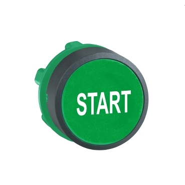
Start marked head PB Ø22-flush spring return
Mfr. Part No.:
ZB5AA333
APT Stock No.:
SE-ZB5AA333
Brand:
SCHNEIDER ELECTRIC
In Stock: available
Need additional quantities?
Contact us for estimated lead timeSubtotal (1 unit)**
GHS 93.90
(Exc. VAT)
GHS 112.68
(Inc. VAT)
Available For Order
* Delivery dates may change based on your quantity and address.
Shipping & Policy
Payment Methods:



Shipping Cost:
Contact the supplier about freight and estimated delivery time.
Secure payments:
Every payment you make on aptghana.com is protected by the platform.
Return policy
Enjoy peace of mind with our 7-day return policy for used items, provided they are returned in their original packaging.
Quick and easy assembly and disassembly
Robustness to withstand harsh environments
With various types of connection: screw clamp, connector, Faston connector, spring terminal, or printed circuit board
A wide choice of contact blocks for general purposes or specific applications (low current, standard)
Excellent mechanical connection with operator head
Description

Shipping & Policy
Payment Methods:
Shipping Cost:
Contact the supplier about freight and estimated delivery time.
Secure payments:
Every payment you make on aptghana.com is protected by the platform.
Return policy
Enjoy peace of mind with our 7-day return policy for used items, provided they are returned in their original packaging.
Specifications
Dimensions Drawings

Mounting and Clearance

(1) Diameter on finished panel or support
(2) For selector switches and Emergency stop buttons, use of an anti-rotation plate type ZB5AZ902 is recommended.
(3) Ø22.5 mm recommended (Ø22.3 0+0.4) / Ø0.89 in. recommended (Ø0.88 in. 0+0.016)
Connections | a in mm | a in in. | b in mm | b in in. |
|---|---|---|---|---|
By screw clamp terminals or plug-in connector | 40 | 1.57 | 30 | 1.18 |
By Faston connectors | 45 | 1.77 | 32 | 1.26 |
On printed circuit board | 30 | 1.18 | 30 | 1.18 |

(1) Diameter on finished panel or support
(2) For selector switches and Emergency stop buttons, use of an anti-rotation plate type ZB5AZ902 is recommended.
(3) Ø22.5 mm recommended (Ø22.3 0+0.4) / Ø0.89 in. recommended (Ø0.88 in. 0+0.016)
,

A: 30 mm min. / 1.18 in. min.
B: 40 mm min. / 1.57 in. min.
Dimensions in mm
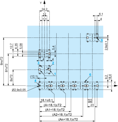
A: 30 mm min.
B: 40 mm min.
Dimensions in in.
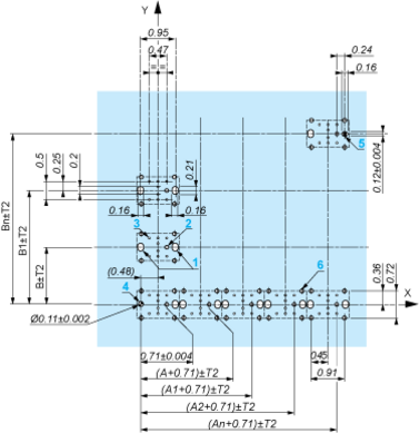
A: 1.18 in. min.
B: 1.57 in. min.
The cumulative tolerance must not exceed 0.3 mm / 0.012 in.: T1 + T2 = 0.3 mm max.
Minimum thickness of circuit board: 1.6 mm / 0.06 in.
Cut-out diameter: 22.4 mm ± 0.1 / 0.88 in. ± 0.004
Orientation of body/fixing collar ZB5AZ009: ± 2°30’ (excluding cut-outs marked a and b).
Tightening torque of screws ZBZ006: 0.6 N.m (5.3 lbf.in) max.
Allow for one ZB5AZ079 fixing collar/pillar and its fixing screws:
every 90 mm / 3.54 in. horizontally (X), and 120 mm / 4.72 in. vertically (Y).
with each selector switch head (ZB5AD•, ZB5AJ•, ZB5AG•).
The fixing centers marked a and b are diagonally opposed and must align with those marked 4 and 5.
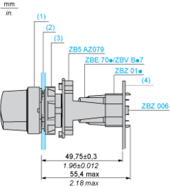
(1) Head ZB5AD•
(2) Panel
(2) Nut
(4) Printed circuit board
1 2 elongated holes for ZBZ006 screw access
2 1 hole Ø 2.4 mm ± 0.05 / 0.09 in. ± 0.002 for centring adapter ZBZ01•
3 8 × Ø 1.2 mm / 0.05 in. holes
4 1 hole Ø 2.9 mm ± 0.05 / 0.11 in. ± 0.002, for aligning the printed circuit board (with cut-out marked a)
5 1 elongated hole for aligning the printed circuit board (with cut-out marked b)
6 4 holes Ø 2.4 mm / 0.09 in. for clipping in adapter ZBZ01•
Dimensions An + 18.1 relate to the Ø 2.4 mm ± 0.05 / 0.09 in. ± 0.002 holes for centring adapter ZBZ01•.
Technical Description
,

,

,
1 N/O

1 N/C

1 N/O + N/C or 1 N/O + N/O or 1 N/C + N/C

,
Single contact

Double contact

Light block

Possible location